 Français
  English
  Español
  Português
  Deutsch
  Italiano
  Русский
  中文
中文  日本語
日本語  العربية
  हिन्दी
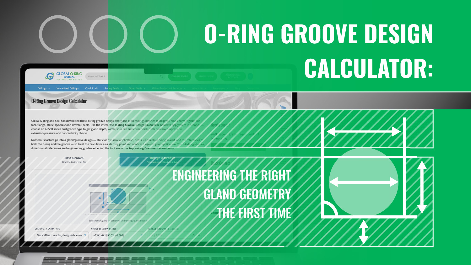
Correct O-ring groove design is a multi-variable problem with tighter tolerances than most engineers initially expect. Squeeze, gland fill, extrusion resistance, and tolerance stack-up all interact — and an error in any one of them can produce leakage, premature elastomer degradation, or catastrophic seal extrusion. Global O-Ring’s O-Ring Groove Design Calculator encodes the published design methodology from the Parker O-Ring Handbook (ORD 5700) and ISO 3601-2 into a free, browser-based tool that resolves gland geometry, validates compression extremes, and checks extrusion pressure limits in real time.
The Engineering Behind Gland Geometry
A properly designed O-ring gland must satisfy three simultaneous constraints:
Diametric squeeze (compression ratio) is the primary sealing mechanism. It’s defined as the difference between the O-ring’s free cross-sectional diameter (W) and the installed gland depth (G), expressed as a percentage of W. Published guidelines from Parker ORD 5700 target roughly 15–25% squeeze for static applications and 10–20% for dynamic — though the exact range varies by cross-section series. Under-squeeze produces insufficient contact stress; over-squeeze accelerates compression set and stress relaxation, especially at elevated temperatures.
Gland fill (volumetric fill ratio) accounts for the fact that rubber is essentially incompressible. The O-ring must have room to deform under compression without hydraulically locking the groove. A typical target range is 75–90% fill at nominal dimensions, leaving a thermal and swell buffer. High-swell applications (e.g., aromatic hydrocarbons with Buna-N) should be designed toward the lower end of that range.
Diametric clearance gap governs extrusion resistance. As system pressure rises, it acts to push the O-ring into the clearance gap between mating components. The maximum safe pressure for a given clearance is a function of gap size, elastomer durometer, and whether pressure is continuous or pulsing. The Parker EB-1010 curves — built into the calculator’s extrusion check — define the failure boundary for standard elastomeric compounds at 70A, 80A, and 90A durometers.
Getting all three right simultaneously is where manual design becomes error-prone, particularly when tolerance extremes are considered.
Calculator Architecture: Two Modes
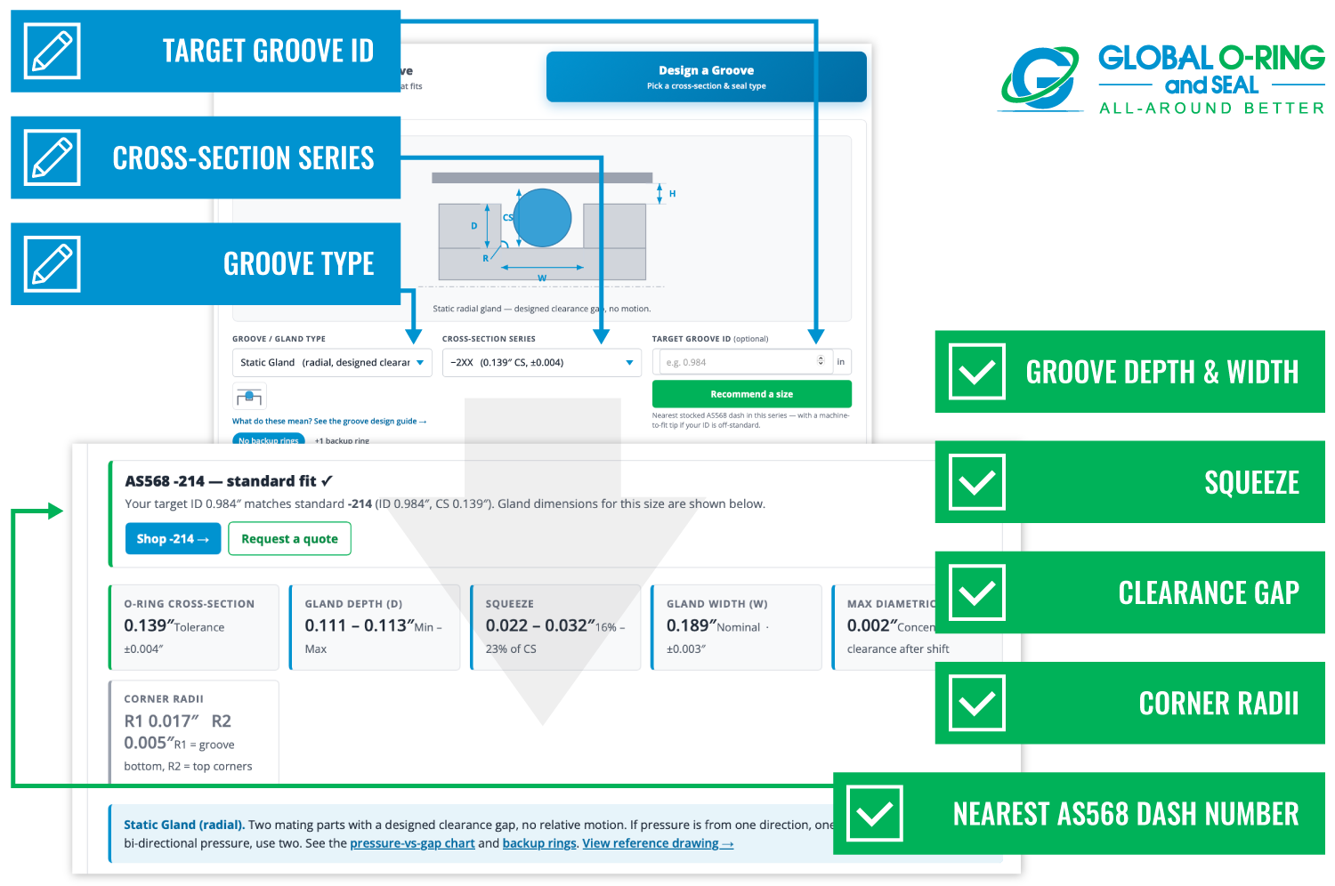
Design a Groove is the forward-design workflow. The engineer selects an AS568 cross-section series (−0XX through −4XX, corresponding to nominal W values of 0.070″ to 0.275″), specifies groove type, and optionally enters a target groove ID. The calculator outputs:
- Groove depth (G) and width (W_g) at nominal dimensions
- Squeeze percentage at nominal, min-tolerance, and max-tolerance conditions
- Clearance gap (H) — with and without backup rings (+1 or +2)
- Corner radii per AS568 gland standards
- Nearest stocked AS568 dash number for the specified ID, with a machining note if the ID falls between standard sizes
Supported groove types are static radial glands, dynamic (reciprocating) glands, flange/face seals, and dovetail face seals. Dynamic glands use reduced squeeze targets and tighter surface finish requirements than static glands; the calculator applies the appropriate values for the selected configuration automatically.
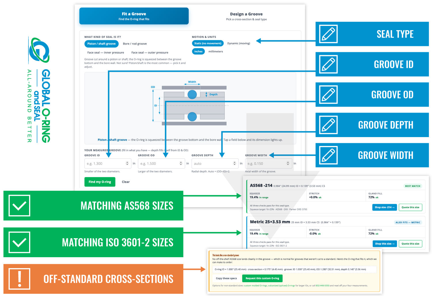
Find the O-Ring for Your Groove operates in reverse — useful for MRO applications, legacy equipment, or non-standard assemblies. The engineer inputs measured groove ID, OD, depth, and width (inch or metric), selects seal type (piston/shaft, bore/rod, inner-pressure face seal, or outer-pressure face seal), and the tool identifies matching AS568 and ISO 3601-2 metric sizes. Each candidate is validated against squeeze, gland fill, and stretch targets before being surfaced as a result. Off-standard cross-sections are flagged as general-guidance only.
The Design Validator
The validator adds three engineering checks that are frequently skipped in manual workflows:
Compression Check evaluates squeeze at nominal dimensions and at both tolerance extremes. A design that passes at nominal can still produce out-of-spec squeeze — and potential leakage or over-stress — when groove and O-ring tolerances stack unfavorably. This is especially relevant for large-bore face seals, where AS568 O-ring tolerances on the cross-section can be ±0.005″ or more.
Extrusion/Pressure Check accepts working pressure (psi), O-ring durometer, and diametric clearance gap as inputs, then returns the maximum allowable pressure for that combination per Parker EB-1010 methodology. If the design falls outside safe limits, it surfaces immediately — before parts are machined. Note that the EB-1010 curves apply to standard elastomers (Buna-N, FKM, EPDM) at room temperature under continuous pressure; pulsing pressure, elevated temperature, FFKM, PTFE, or polyurethane compounds require a separate engineering review.
Concentricity/Clearance Helper calculates worst-case diametric clearance from bore ID and shaft/piston OD inputs, assuming full eccentricity (all clearance shifted to one side). This is the conservative input the extrusion check requires and the value that often gets underestimated when designers use nominal fit tolerances instead of worst-case stack-up.
Standards Compliance and Limitations
Inch gland dimensions follow the AS568 design tables in Parker ORD 5700. Metric gland dimensions follow ISO 3601-2 housing specifications. All matched sizes are checked against Global O-Ring’s stocked inventory in Houston, connecting design output directly to available product.
The calculator is intentionally scoped to standard elastomeric compounds in conventional service conditions. It does not model fluid swell, thermal expansion, compression set over time, or fatigue under dynamic cycling — all of which require application-specific engineering judgment. For critical applications, the tool’s output should be treated as a validated starting point, not a final specification.
Access and Support
The O-Ring Groove Design Calculator is available at https://www.globaloring.com/o-ring-groove-design/ at no cost. For designs that fall outside the tool’s standard scope — high-pressure hydraulics, cryogenic service, rapid gas decompression, or specialty compounds — Global O-Ring’s engineering team is available at 832-448-5550 or via the RFQ page. Most stocked sizes ship same day from Houston.