 English
  Español
  Français
  Português
  Deutsch
  Italiano
  Русский
  中文
中文  日本語
日本語  العربية
  हिन्दी
 O-Ring Groove Design Overview
Global O-Ring and Seal has developed o-ring groove design and gland dimension guidelines. These are intended for use in basic design consideration and to understand the core principles involved in o-ring gland/groove design. Numerous factors go into the appropriate design of a gland/groove including but not limited to static or dynamic applications, pressure conditions, fluid characteristics being sealed, and tolerances of both the o-ring and groove.
Finding the Right O-Ring Cross-Section
The o-ring cross-section in your design will determine all your subsequent dimensions and specifications. Standard o-rings are available in various cross-sections and inside dimensions (ID). For example, an o-ring with an ID of 5 ¼ can be purchased in four standard AS568 cross-sections. Below, is a list of advantages in the selection of smaller and larger cross-section o-rings.
Advantages of Smaller Cross-Section O-Rings
- Compact and lighter-weight o-ring
- Most cost-effective if the design uses expensive elastomers such as FKM or FFKM
- Reduced machining of grooves
Advantages of Larger Cross-Section O-Rings
- Smaller required squeeze to create a seal which reduces compression set issues
- Greater tolerances variations in the machined groove while maintaining acceptable compression squeeze
ID/OD Interference
The ID or OD of the o-ring should be sized to create some interference, per the guidelines below:
- Piston Gland Seals: The ID of the o-ring should be smaller than the OD of the gland so the installed o-ring is always slightly stretched (max 5%)
- Rod Gland Seals: The o-ring OD should be slightly larger than the ID gland depth (max 2%)
- External Pressure Face Seals: The o-ring ID should be slightly smaller than the gland inner diameter (Gland ID) (max 5%)
- Internal Pressure FaceSeals: The o-ring OD should be slightly larger than the gland outer diameter (Gland OD) (max 3%)
O-Ring Groove/Gland Types
Below, four standard application groove design guidance tables are presented along with dimensional reference drawings. The first table is for industrial face or flange seals. The second table is for static industrial radial applications. The third table is for dynamic industrial reciprocating applications. Lastly, the fourth table is for dovetail groove design. These o-ring groove design guides offer default dimensional guidance for basic o-ring groove design applications.
Flange/Face Seal
A flange or face seal is static and will not have a gap between surfaces, eliminating any design issues associated with extrusion. This is the most straightforward of groove designs.
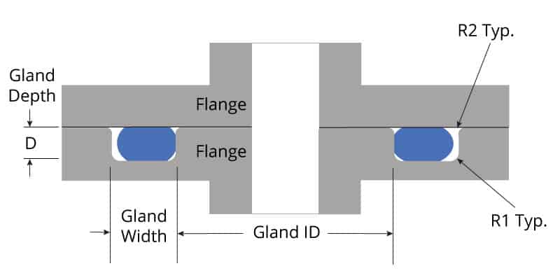
| AS568 Series | O-Ring Cross-Section | Gland Depth (D) | Squeeze | Gland Width (W) Liquids | Gland Width (W) Vacuum & Gases | Gland Corner Radii | |||||
|---|---|---|---|---|---|---|---|---|---|---|---|
| Nominal | TOL (+/-) | Actual | Percent | Nominal | TOL (+/-) | Nominal | TOL (+/-) | R1 | R2 | ||
| -0XX | 0.070 | 0.003 | .055-0.057 | .010-.018 | 15%-25% | 0.103 | 0.002 | 0.084 | 0.003 | 0.010 | 0.005 |
| -1XX | 0.103 | 0.004 | .088-.090 | .010-.018 | 10%-17% | 0.140 | 0.003 | 0.121 | 0.003 | 0.010 | 0.005 |
| -2XX | 0.139 | 0.004 | .121-.123 | .012-.022 | 9%-16% | 0.180 | 0.003 | 0.160 | 0.003 | 0.018 | 0.005 |
| -3XX | 0.210 | 0.005 | .185-.188 | .017-.030 | 8%-14% | 0.280 | 0.003 | 0.240 | 0.003 | 0.028 | 0.005 |
| -4XX | 0.275 | 0.006 | .237-.240 | .029-.044 | 11%-16% | 0.352 | 0.003 | 0.310 | 0.003 | 0.028 | 0.005 |
Dovetail Face Seal
A dovetail face seal is a special static gland designed to retain the o-ring in the groove. This design is beneficial when the seal is opened and closed during use.
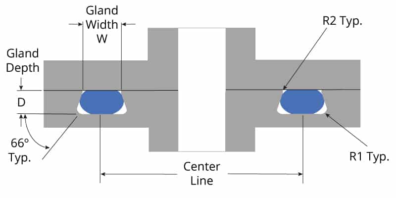
| AS568 Series | O-Ring Cross-Section | Gland Depth (D) | Gland Width (W) | Gland Corner Radii | ||||
|---|---|---|---|---|---|---|---|---|
| Nominal | TOL (+/-) | Nominal | TOL (+/-) | Nominal | TOL (+/-) | R1 | R2 | |
| -0XX | 0.070 | 0.003 | 0.052 | 0.002 | 0.064 | 0.002 | 0.015 | 0.005 |
| -1XX | 0.103 | 0.004 | 0.078 | 0.003 | 0.088 | 0.003 | 0.015 | 0.01 |
| -2XX | 0.139 | 0.004 | 0.106 | 0.003 | 0.120 | 0.003 | 0.031 | 0.01 |
| -3XX | 0.210 | 0.005 | 0.164 | 0.004 | 0.176 | 0.003 | 0.031 | 0.015 |
| -4XX | 0.275 | 0.006 | 0.215 | 0.004 | 0.235 | 0.003 | 0.063 | 0.015 |
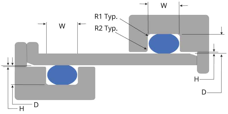
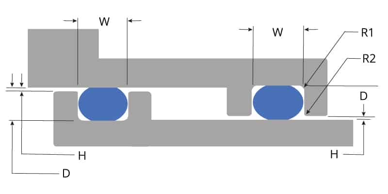
Static Gland Seal
A static gland seal is used when two mating components have a designed gap between surfaces. Typically, these applications involve designs involving one mating part being inserted into another part requiring design clearances.
| AS568 Series | O-Ring Cross-Section | Gland Depth (D) | Squeeze | Gland Width (W) | Gap (H) | Gland Corner Radii | ||||||
|---|---|---|---|---|---|---|---|---|---|---|---|---|
| Nominal | TOL (+/-) | Actual | Percent | Nominal | TOL (+/-) | w/ 1 Backup Ring | w/ 2 Backup Rings | MAX | R1 | R2 | ||
| -0XX | 0.070 | 0.003 | .050-0.052 | .015-.023 | 22%-32% | 0.095 | 0.002 | 0.140 | 0.207 | 0.002 | 0.007 | 0.005 |
| -1XX | 0.103 | 0.004 | .081-.083 | .017-.025 | 17%-24% | 0.142 | 0.003 | 0.173 | 0.240 | 0.002 | 0.007 | 0.005 |
| -2XX | 0.139 | 0.004 | .111-.113 | .022-.032 | 16%-23% | 0.189 | 0.003 | 0.210 | 0.277 | 0.002 | 0.017 | 0.005 |
| -3XX | 0.210 | 0.005 | .170-.173 | .032-.045 | 15%-21% | 0.283 | 0.003 | 0.313 | 0.412 | 0.003 | 0.027 | 0.005 |
| -4XX | 0.275 | 0.006 | .226-.229 | .040-.055 | 15%-20% | 0.377 | 0.003 | 0.410 | 0.540 | 0.003 | 0.027 | 0.005 |
Dynamic Gland Seal
A dynamic gland seal is used when two mating components are moving in relation to each other while maintaining a seal. There will always be a gap between the two surfaces.
| AS568 Series | O-Ring Cross-Section | Gland Depth (D) | Squeeze | Gland Width (W) | Gap (H) | Gland Corner Radii | ||||||
|---|---|---|---|---|---|---|---|---|---|---|---|---|
| Nominal | TOL (+/-) | Actual | Percent | Nominal | TOL (+/-) | w/ 1 Backup Ring | w/ 2 Backup Rings | MAX | R1 | R2 | ||
| -0XX | 0.070 | 0.003 | .055-0.057 | .010-.018 | 15%-25% | 0.095 | 0.002 | 0.140 | 0.207 | 0.002 | 0.007 | 0.005 |
| -1XX | 0.103 | 0.004 | .088-.090 | .010-.018 | 10%-17% | 0.142 | 0.003 | 0.173 | 0.240 | 0.002 | 0.007 | 0.005 |
| -2XX | 0.139 | 0.004 | .121-.123 | .012-.022 | 9%-16% | 0.189 | 0.003 | 0.210 | 0.277 | 0.002 | 0.017 | 0.005 |
| -3XX | 0.210 | 0.005 | .185-.188 | .017-.030 | 8%-14% | 0.283 | 0.003 | 0.313 | 0.412 | 0.003 | 0.027 | 0.005 |
| -4XX | 0.275 | 0.006 | .237-.240 | .029-.044 | 11%-16% | 0.377 | 0.003 | 0.410 | 0.540 | 0.003 | 0.027 | 0.005 |
Groove Design Considerations
The design tables displayed above were created using best practices, including Compression Ratio, O-Ring Extrusion, Concentricity and Diametric Gap, and Backup Rings.
Compression Ratio
Our guidelines start with the nominal (or stated) dimension, then incorporate tolerances of the design elements to provide the correct basis for designing the gland/groove. Note: The designer will be making trade-offs between dimensional parameters. Ultimately, the final design must handle the extremes of tolerances.
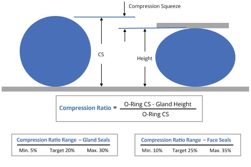
In the calculation above, we used the nominal (or stated) dimensions. However, when designing the groove, it’s necessary to look at the two extreme cases. First, the o-ring is at its upper tolerance limit and the gland height is at its lower tolerance limit. Secondly, the o-ring is at its smallest cross-section tolerance limit and the gland is at its largest size tolerance limit. These will produce the highest compression and lowest compression percentages. All three compression values must fall between 5%-30% squeeze.
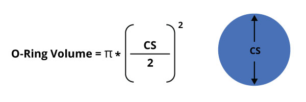
Calculating O-Ring Gland Dimensions
The gland retaining the o-ring has a rectangular area. Once the o-ring cross-section is selected and the gland height is calculated (to achieve the desired squeeze to the o-ring), the final calculation will be the gland width. To find the minimum area necessary, calculate the total volume of the o-ring which creates the rectangle to hold that volume. Below, is the formula to calculate the volume of the o-ring based on the cross-section.
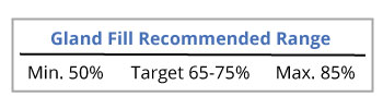 The target gland fill recommendations incorporate several factors that could impact the volume necessary to house the o-ring. These factors include room for thermal expansion, swell due to fluid exposure, and the effect of tolerance variations in the machined groove and molded o-ring.
O-Ring Extrusion
Extrusion is a concern for radial seals where a designed gap exists between moving components: Either the piston and bore, or the rod and bore. The issue is that at higher pressures from one direction, the o-ring can be forced into the small gap and get damaged. The overall design of the sealing system must take into consideration this design gap.
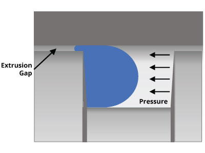
Concentricity and Diametric Gap
In the sealing design, unless the bore and piston (or rod) are ensured to remain concentric by bearings, it must be assumed that all the gap possible can shift to one side. This is the gap used when designing for extrusion.
![]()
Design Limits for Extrusion
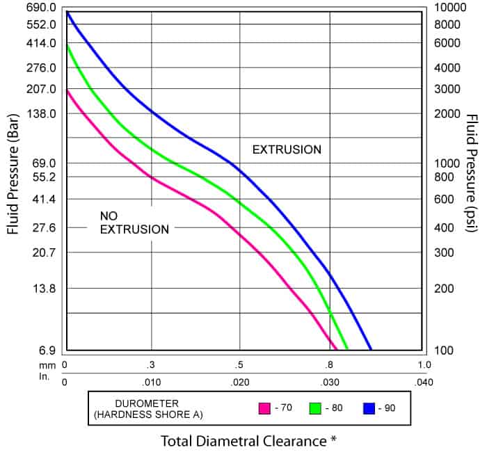
Many design elements can be used to address extrusion issues in sealing design. If the maximum allowable gap is decreased through alignment/bearings, this allows for an increase in pressure for the same o-ring. Another option is increasing the durometer (hardness) of the compound, which increases the allowable pressure for a defined gap. To read more about the elements involved in o-ring pressure tolerance, click here.
Another alternative is to use backup rings which are anti-extrusion elements. Backup rings are made of thin, hard plastic materials such as Nylon, PTFE, and PEEK. Backup rings work by covering the existing gap. Below, is an extrusion chart providing the pressure limits by gap and durometer of o-ring. If the trade-offs of gap design and durometer do not work, the use of backup rings are recommended to overcome extrusion issues.
Backup Ring Layouts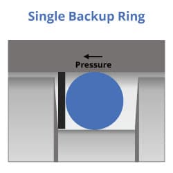
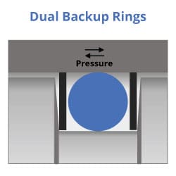
Backup rings are designed to eliminate the extrusion gap in high-pressure sealing applications. If the pressure is from a single direction, only one backup ring is necessary. If the pressure is from both directions, it’s recommended a backup ring be placed on both sides of the o-ring. The addition of backup rings should be incorporated in the fill calculation for determining the groove width. Finally, backup rings can either be flat (solid, split, or spiral) or contoured.